Main menu Open search

Blog

How to Choose the Right Mesh Cable Tray?

Choosing the right mesh cable tray affects cable safety, installation speed, and long-term maintenance. A suitable tray should match the cable load, support span, installation environment, and future expansion plans. It is not simply a matter of selecting the widest or strongest model.

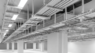
A mesh cable tray can improve ventilation and reduce dust collection around power and data cables. Its open structure also makes inspection easier, especially in crowded ceiling spaces. However, the design still needs careful evaluation. Check wire diameter, load capacity, surface finish, connection strength, and available fittings. Galvanized steel may suit ordinary indoor areas, while stainless steel can offer better resistance in humid or corrosive locations. Small details matter.

Think beyond the first installation.

Experienced installers often measure the route twice, then review access points before ordering materials. Tight corners, uneven supports, and limited working space can change the best choice. Cable separation may also be necessary to reduce interference between power and communication circuits. Local electrical requirements and manufacturer data should guide the final decision.

No tray fits every project.

A practical selection balances safety, cost, appearance, and maintenance access. It should support today’s cables without creating unnecessary weight or expense. It should also leave room for tomorrow’s changes. Even experienced teams can overlook spare capacity or grounding details. Careful review helps expose these weaknesses before installation begins. This guide explains the main factors, common mistakes, and field considerations involved in choosing a reliable mesh cable tray.

How to Choose the Right Mesh Cable Tray?

Define Cable Fill: NEC 392.22 Allows 40%, 30%, or 50% Capacity

How to Choose the Right Mesh Cable Tray?

Define Cable Fill: NEC 392.22 Allows 40%, 30%, or 50% Capacity

Cable fill is the starting point for selecting a mesh cable tray. Under NEC 392.22, permitted fill can be 40%, 30%, or 50%, depending on cable type, conductor arrangement, and tray design. The 2023 National Electrical Code, published through NFPA, requires designers to verify the applicable calculation rather than use one universal percentage. A tray that looks spacious may still fail the calculation.

Measure the cable’s actual outside diameter, not only its conductor size. Add the cross-sectional areas of all cables, then compare the total with the tray’s usable interior area. For example, a 100 mm-wide tray with 50 mm of usable height provides 5,000 mm² before applying the permitted fill ratio. At 40%, the working limit becomes 2,000 mm². Keep future expansion in mind. The 2023 AFCOM State of the Data Center report highlights continuing pressure for higher-density infrastructure, making spare capacity increasingly practical. My view is simple: strict code compliance alone may not create a serviceable installation.

Tips: Confirm cable classification with the manufacturer’s data sheet. Separate power and communication cables when required. Check bend radius at every turn. Recalculate after field changes. A rushed 50% assumption can become an expensive correction. Use a qualified electrical designer for final verification under the adopted local code.

How to Choose the Right Mesh Cable Tray?

NEC 392.22 defines the maximum cable fill for different cable types and sizes.

Cable fill is calculated by comparing the total cross-sectional area of the cables with the usable interior area of the cable tray. Under NEC 392.22(B), allowable fill commonly ranges from 30% to 50%: 30% for smaller single-conductor cables, 40% for larger single-conductor or multiconductor cables, and 50% for smaller multiconductor or control and signal cables. Always verify the applicable NEC edition and installation conditions before final selection.

Match Span and Load with NEMA VE 1 Tables, Not Width Alone

How to Choose the Right Mesh Cable Tray?

Mesh cable tray selection should begin with span and load, not width alone. A wide tray can still fail when supports are spaced too far apart. NEMA VE 1-2017 classifies tray capacity by load ratings from 50 to 150 pounds per linear foot and by support spans. These values are not interchangeable. A tray rated for a 12-foot span may require a lower working load than the same tray supported every 6 feet.

Measure the real installation conditions. Include cable weight, future additions, fittings, vertical drops, and concentrated loads from maintenance work. NEMA VE 1 tables provide a consistent comparison, while IEC 61537:2023 addresses cable tray mechanical performance and testing. For example, if the installed cables weigh 80 pounds per foot, selecting a 100-pound-per-foot class may appear reasonable. Yet a long span, seismic movement, or a heavy cable bundle near one edge can reduce the practical margin. That detail is easy to miss.

Width still matters, but it comes later. Keep cables separated according to their voltage, heat, and installation requirements. Then verify the selected mesh tray’s loading at the actual support spacing. Field measurements are useful. However, they are not a substitute for structural calculations. I have seen designs pass a width check and fail a span review. Recheck the assumptions before ordering.

How to Choose the Right Mesh Cable Tray? Match Span and Load with NEMA VE 1 Tables, Not Width Alone
Selection Dimension What to Check Reference or Calculation Practical Selection Guidance
1. Define the Installation Requirement
Support span Distance between adjacent supports, measured along the tray run. Typical NEMA VE 1 reference spans include 4, 5, 6, 8, 10, and 12 ft. Use the actual support spacing. Do not select a tray using a shorter span than the installation requires.
Cable load Combined weight of cables, conductors, accessories, and any permitted future capacity. Design load = installed cable load + planned spare capacity Calculate the load in lb/ft or kg/m before choosing tray width or mesh diameter.
Service environment Indoor, outdoor, corrosive, wet, dusty, high-temperature, or wash-down conditions. Confirm material, finish, corrosion resistance, and temperature limitations separately from structural load. A suitable load rating does not automatically make a tray suitable for the environment.
2. NEMA VE 1 Load/Span Classification Reference
NEMA VE 1 Load Class Minimum Rated Load at the Designated Span Approximate Metric Equivalent Use in the Selection Process
8A 50 lb/ft 74.4 kg/m Choose when the calculated design load is no greater than the verified tray rating at the required span.
8B 75 lb/ft 111.6 kg/m Provides a higher load category than 8A; still verify the exact span and product test data.
8C 100 lb/ft 148.8 kg/m Suitable only when the tray assembly is verified for the required span and loading condition.
8D 125 lb/ft 186.0 kg/m Use for higher cable concentration where the selected tray has matching span-specific test evidence.
8E 150 lb/ft 223.2 kg/m Consider when the calculated load, future allowance, and support spacing require this capacity.
8F 175 lb/ft 260.4 kg/m Higher-capacity category; check splice plates, supports, fasteners, and installation conditions as a system.
8G 200 lb/ft 297.6 kg/m Use only when the complete tray system is documented for this load level and required span.
3. Load Calculation Example
Installed cable load Example: 34 cables averaging 1.4 lb/ft each 34 × 1.4 lb/ft = 47.6 lb/ft Use the combined linear load, not the number of cables alone.
Future capacity allowance Example planning allowance: 25% 47.6 × 1.25 = 59.5 lb/ft Include expected cable additions where the project specification requires spare capacity.
Required structural capacity Calculated design load for the example 59.5 lb/ft ≈ 88.5 kg/m A tray rated at 50 lb/ft would not satisfy this example; a higher verified load class is required.
4. Width Is a Cable-Fill Dimension, Not a Structural Rating
Width Decision Primary Question Why It Matters Recommended Action
Narrow tray Will all cables fit without excessive crowding? Overcrowding can restrict ventilation, complicate installation, and reduce future flexibility. Calculate cable area or bundle arrangement and maintain the project-specified fill limit.
Wide tray Can the tray and supports carry the load over the actual span? Increasing width may increase cable quantity and total weight without improving structural capacity. Check width, load class, span, support spacing, and accessories together.
Multiple cable layers Does the installation permit the intended stacking arrangement? Stacking changes the load distribution and may affect thermal performance and cable accessibility. Follow applicable electrical codes, project specifications, and cable manufacturer's requirements.
5. Final Verification Checklist
Span match Is the tray rating documented for the actual support span? Required Reject selections based only on a rating at a shorter span.
Load match Is the rated capacity greater than the calculated design load? Required Select the next appropriate load category when the calculated load is close to the limit.
System components Are supports, splice connections, bends, tees, reducers, and fasteners suitable for the same application? Required Verify the complete installed assembly, not only the straight tray section.
Safety and compliance Does the installation meet the applicable electrical code, project specification, and local requirements? Required Use the latest project-approved standards and installation instructions.
Note: NEMA VE 1 load classes are reference classifications for cable tray systems. Actual capacity depends on the tray construction, material, mesh geometry, support arrangement, span, splice location, loading method, and installation conditions. Always use span-specific, independently verified product data for final design.

Verify Strength Using IEC 61537 SWL Testing and Deflection Criteria

How to Choose the Right Mesh Cable Tray?

Verify Strength Using IEC 61537 SWL Testing and Deflection Criteria

A mesh cable tray should be selected from tested performance, not appearance alone. IEC 61537 provides a recognized framework for evaluating cable tray systems and their safe working load (SWL). The test should reflect the proposed support span, loading method, joints, and fixing arrangement. A tray tested over 1.5 meters may behave differently over 2 meters.

Ask for the complete test conditions. Check the distributed load, support spacing, tray width, connector position, and measured deflection. Do not rely on one SWL figure without this context. Deflection matters because excessive sag can stress cables, disturb clearances, or create an untidy installation. The acceptable limit should match the project specification and the declared test criteria.

Real installations are rarely perfect. Cable bundles may be uneven, and supports may not align precisely. Leave practical capacity above the calculated cable weight. Include future cables, vertical drops, fittings, and installation handling loads where appropriate. A tray can pass a laboratory test yet perform poorly when overloaded in the field.

Inspect the report date and product configuration. Small changes in wire diameter, mesh shape, or connector design can affect stiffness. If the proposed tray differs from the tested assembly, request engineering confirmation before approval. That extra check prevents a confident but costly assumption.

Select Finishes by ISO 12944 Corrosion-Exposure Classification

How to Choose the Right Mesh Cable Tray?

Select Finishes by ISO 12944 Corrosion-Exposure Classification

A mesh cable tray should match its environment, not just its appearance. ISO 12944 classifies atmospheric corrosion from C1 to C5, with CX covering extreme conditions. C1 suits dry, heated interiors. C2 fits protected indoor areas with low humidity. C3 describes ordinary industrial or urban environments. C4 applies to coastal areas, chemical plants, and humid industrial spaces. C5 and CX demand stronger protection.

Finish selection must consider moisture, salt, chemicals, temperature, and expected service life. Zinc coatings can work well in moderate exposure. Hot-dip galvanizing usually offers deeper protection for outdoor steelwork. Duplex systems, such as galvanizing with a compatible coating, may suit severe environments. However, coating thickness and preparation matter as much as the finish name.

Field inspections often reveal small problems first. Cut edges, damaged welds, and trapped water can become early corrosion points. A tray installed near a shoreline may face C5 or CX conditions, even when the building interior seems dry. That judgment needs site evidence. Check humidity, airborne salt, chemical vapors, and cleaning methods before specifying materials. ISO 12944 durability ranges are useful, but they are not guarantees. Real exposure can be harsher than the design estimate. Sometimes, the classification is simply uncertain. Reassess it.

Control Heat: NEC 310.15(C)(1) Rates 4–6 Conductors at 80%

How to Choose the Right Mesh Cable Tray?

Heat control begins with conductor counting. Under NFPA 70, 2023 edition, Table 310.15(C)(1), four to six current-carrying conductors require an 80% adjustment factor. This reduces allowable ampacity before installation conditions are considered. A 100-ampacity conductor may therefore be treated as 80 amps. The rule applies to current-carrying conductors, not simply every cable visible in the tray. Neutral loading and harmonic currents can change the calculation. A spacious tray can still run hot.

Choose a mesh tray with open ventilation, suitable width, and enough room for future circuits. NFPA 70, Article 392, also directs attention to cable-tray ampacity and installation conditions. Check conductor insulation ratings, ambient temperature, grouping, and separation. Do not rely only on the tray’s outside dimensions. Field experience shows that tight bends and bundled cables often defeat good airflow. That assumption needs review.

Tips: Count current-carrying conductors from the actual circuit schedule. Apply the 80% factor before selecting conductor size. Leave visible air gaps between cable groups. Record the calculation beside the tray layout. If harmonic-producing loads are present, ask a qualified electrical professional to verify neutral-current assumptions. The simplest tray is not always the coolest one.

Exclusive Access

Unlimited Resources

Detailed information on our products to assist you with the planning of your cable management project

Register Now

BIM Files

Step Files

Installation Manuals

User Guides

Best Practice Guides

Technical Charts